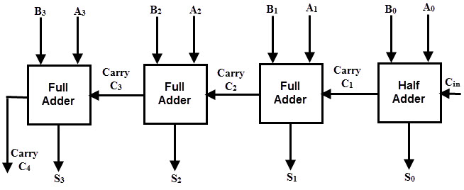
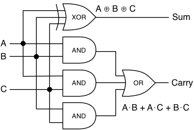
Design a 3 bit full adder circuit using pld
Normal Formulas; Canonical Formulas: Minterm Canonical Formulas, m-Notation; Manipulations of Boolean Formulas: Equation Complementation, Expansion about a Variable, Equation Simplification, The Reduction Version papier du livre.

Boolean Algebra and Combinational NetworksPrinciple of Duality; Boolean Formulas and Functions: Equation Complementation, Expansion about a Variable, Equation Simplification, The Reduction Theorems, Minterm Canonical Formulas, Maxterm Canonical Formulas, Complements of Canonical Formulas; Gates and Combinational Networks: Gates, Combinational Networks, Analysis Procedure, Synthesis Procedure, A Logic Design Example; Incomplete Boolean Functions and Don't Care Conditions: Describing Incomplete Boolean Functions, Don't Care Conditions in Logic Design; Additional Boolean Operations and Gates: The NAND-Functions, The NOR-Functions, Universal Gates, NAND-Gate Realizations, NOR-Gate Realizations, The Exclusive-OR-Function, The Exclusive-NOR Function.
Simplification of Boolean ExpressionsFormulation of the Simplification Problem: Criteria of Minimality, The Simplification Problem; Prime Implicants and Irredundant Disjunctive Expressions: Implies, Subsumes, Implicants and Prime Implicants, Irredundant Disjunctive Normal Formulas; Prime Implicants and Irredundant Conjunctive Expressions; Karnaugh Maps: One-Variable and Two-Variable Maps, Three-Variable and Four-Variable Maps, Karnaugh Maps and Canonical Formulas, Product and Sum Term Representations on Karnaugh Maps; Using Karnaugh Maps to Obtain Minimal Expressions for Complete Boolean Functions: Prime Implicants and Karnaugh Maps, Essential Prime Implicants, Minimal Sums, Minimal Products; Minimal Expressions of Incomplete Boolean Functions: Minimal Sums, Minimal Products; The Quine-McCluskey Method of Generating Prime Implicants and Prime Implicates: Essential Prime Implicants, Column and Row Reductions, A Prime - Implicant Selection Procedure; Decimal Method for Obtaining Prime Implicants; Map Entered Variables.
Logic Levels and FamiliesLogic Levels, Integration Levels; Output Switching Times, The Propagation Delay, Fan-out and Fan-in, Extension to Other Logic Gates, Logic Cascades.
Implementation of ROMs and PLAsTransistor-Transistor logic; Wired logic, TTL with Totem-Pole output, Thee-state output TTL, Schottky TTL; The MOS Field-Effect-Transistor: Operation of n-Channel, Enhancement-Type MOSFET, The n-Channel Depletion-Type MOSFET, The p-channel MOSFETs, Circuit Symbols, The MOSFET as a Resistor; NMOS and PMOS Logic: The NMOS Inverters, NMOS NOR-Gate, NMOS NAND-Gate, PMOS Logic, performance; The CMOS Inverter, CMOS NOR-Gate, CMOS NAND-Gate, performance, Comparison of the above logic families.
Logic Design with MSI Components and Programmable Logic DevicesBinary Adders and Subtractors; Binary Subtractors, Carry Lookahead Adders; Decimal Adders; Comparators; Decoders; Logic Design Using Decoders; Decoders with an Enable Input; Encoders; Multiplexers; Logic Design with Multiplexers; Programmable Logic Devices PLDs ; PLD Notation; Programmable Read-Only Memories PROMs ; Programmable Logic Arrays PLAs ; Programmable Array Logic PAL Devices.
Flip-Flops and Simple Flip-Flop ApplicationsThe Basic Bistable Element; Latches; The SR Latch, An Application of the SR Latch: A Switch Debouncer, The SR Latch, The Gated SR Latch, The Gated D Latch; Master-Slave Flip-Flops Pulse-Triggered Flip-Flops ; The Master-Slave SR Flip-Flop; The Master-Slave JK Flip-Flop; Edge-Triggered Flip-Flop; The Positive Edge-Triggered D Flip-Flop; Negative Edge-Triggered D flip-flops; Characteristic Equations; Registers; Counters: Binary Ripple Counters, Synchronous Binary Counters, Counters Based on Shift Registers ; Design of Synchronous Counters: Design of a Synchronous Mod-6 Counter Using Clocked JK Flip-Flops, Design of a Synchronous Mod-6 Counter Using Clocked D,T or SR Flip-Flops.
Page not found
Synchronous Sequential NetworksStructure and Operation of Clocked Synchronous Sequential Networks; Analysis of Clocked Synchronous Sequential Networks; Excitation and Output Expressions, Transition Equations, Transition Tables, Excitation Tables, State Tables, State Diagrams Network Terminal Behavior.
Review Questions Sectionwise 1.

Solved Examples 2 Review Questions Sectionwise 2 Chapter4 logic Design with MSI Components PLDs. Chapter5 RipFlop Simple jipflop Applications. Chapter6 Synchronous Sequential Networks.

Contents Chapter1 Boolean Algebra and Combinational Networks 1. Chapter2 Simplification of Boolean Expressions. Chapter3 Logic Levels and Families Chapter4 Logic Design with MSI Components PLDs FlipFlop Simple FlipFlop Applications Chapter6 Synchronous Sequential Networks Combinational Logic Circuits Boolean Godse Technical Publications , - pages 0 Avis Boolean Algebra and Combinational NetworksPrinciple of Duality; Boolean Formulas and Functions: Chapter1 Boolean Algebra Combinational Networks.